Welcome to Lulua-Dubai Company
Discover Quality, Experience Excellence
Discover Quality, Experience Excellence
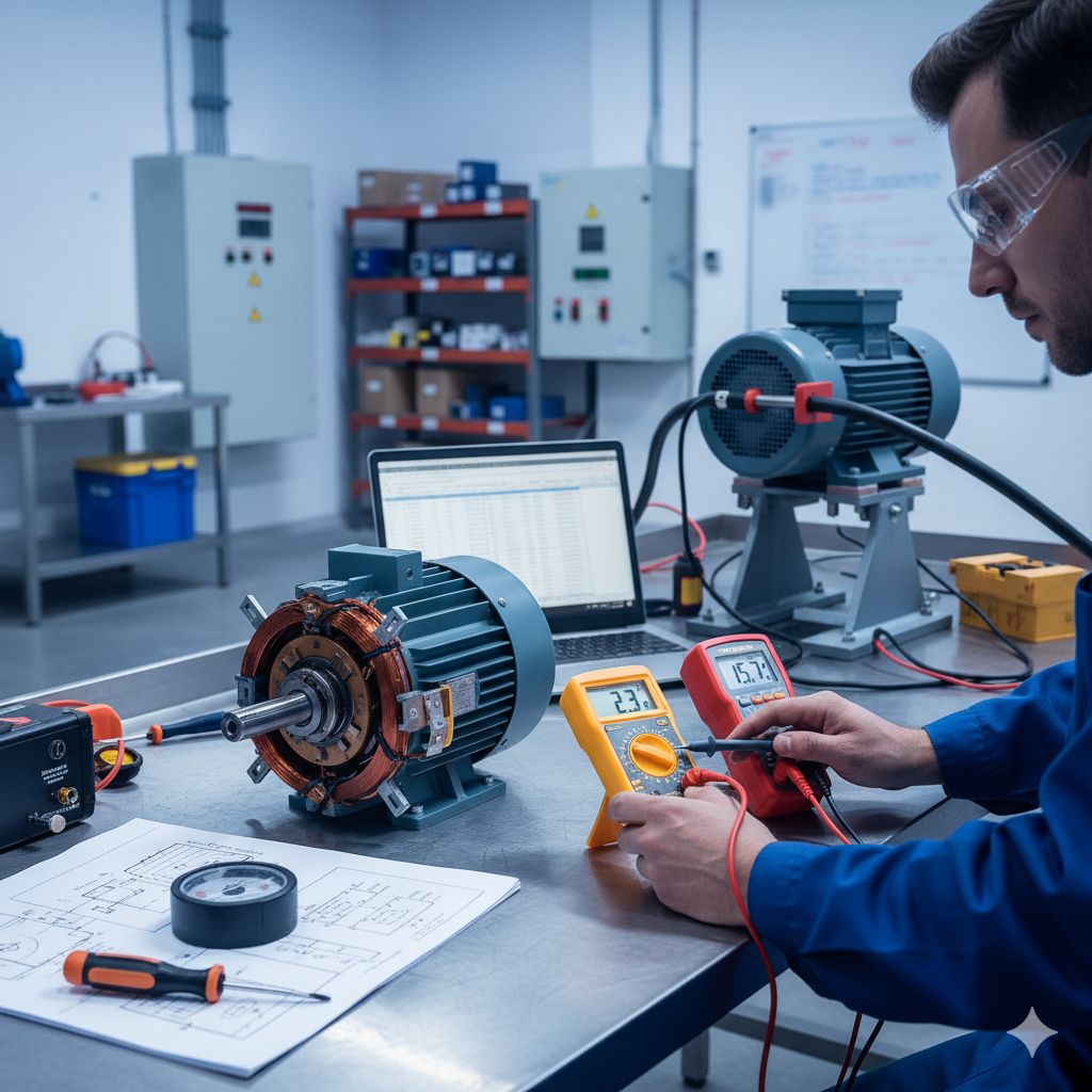
Measuring the electrical characteristics of single-phase and three-phase motors is crucial for understanding their performance, troubleshooting issues, and ensuring safe operation. While the fundamental principles are similar, the approach differs due to the varying power supply configurations.
Measuring Single-Phase Motors
Single-phase motors are commonly found in household appliances and small industrial applications. They operate on a single alternating current (AC) waveform.
1. Voltage Measurement:
Tool: Digital Multimeter (DMM)
Procedure: Set the DMM to AC voltage mode. Connect the test leads across the motor's power input terminals (line to neutral). Ensure the motor is running under its normal operating conditions.
Importance: Verify that the supply voltage matches the motor's rated voltage. Deviations can lead to overheating or underperformance.
2. Current Measurement:
Tool: Clamp Meter or DMM with current clamp accessory.
Procedure: Set the clamp meter to AC current mode. Clamp it around one of the motor's power supply wires (either line or neutral). Never clamp across both wires simultaneously.
Importance: Measure the operational current. Compare it to the motor's full-load ampere (FLA) rating on its nameplate. Current exceeding FLA indicates an overload, mechanical issue, or incorrect voltage.
3. Resistance Measurement (for winding health):
Tool: DMM (ohmmeter function)
Procedure: ENSURE THE MOTOR IS COMPLETELY DISCONNECTED FROM POWER. Discharge any capacitors. Measure the resistance between the motor's main winding terminals and between the start winding terminals (if applicable). Also, check for continuity between the windings and the motor frame (ground).
Importance: Low resistance values (typically a few ohms) are normal for windings. Open circuits indicate a broken winding, while very low resistance or a short to ground indicates a serious insulation breakdown.
4. Power Measurement:
Tool: Power Meter or Power Quality Analyzer.
Procedure: These devices connect in-line with the motor's power supply and simultaneously measure voltage, current, and power factor.
Importance: Provides real power (Watts), apparent power (VA), and reactive power (VARs). The power factor (PF) is vital; a low PF indicates inefficient operation, often due to an underloaded motor or poor power factor correction.
5. Speed Measurement:
Tool: Tachometer (contact or non-contact).
Procedure: For contact tachometers, touch the rotating shaft. For non-contact, aim the laser at a reflective marker on the shaft.
Importance: Verify the motor's actual operating speed against its rated RPM. Slip (difference between synchronous and actual speed) indicates load conditions.
Measuring Three-Phase Motors
Three-phase motors are common in industrial settings due to their efficiency and robust design. They operate on three alternating current waveforms, typically 120 degrees out of phase with each other.
1. Voltage Measurement:
Tool: DMM
Procedure: Set the DMM to AC voltage mode. Measure the line-to-line voltage between each pair of the three phases (L1-L2, L2-L3, L3-L1). Also, measure line-to-ground voltage if applicable.
Importance: All three line-to-line voltages should be balanced and close to the motor's rated voltage. Voltage imbalance (more than 1-2%) can cause overheating and motor damage.
2. Current Measurement:
Tool: Clamp Meter
Procedure: Set the clamp meter to AC current mode. Clamp it around each of the three individual phase wires (L1, L2, L3).
Importance: All three phase currents should be relatively balanced. Significant current imbalance (more than 5-10%) can indicate a voltage imbalance, a fault in the motor windings, or a mechanical problem with the load. Compare readings to the motor's FLA.
3. Resistance Measurement (for winding health):
Tool: DMM (ohmmeter function)
Procedure: ENSURE THE MOTOR IS COMPLETELY DISCONNECTED FROM POWER. Discharge any capacitors. Measure the resistance between each pair of phases (L1-L2, L2-L3, L3-L1). For wye-connected motors, you'll measure phase-to-phase. For delta, you'll also measure phase-to-phase directly across winding sections. Also, check for continuity between each winding and the motor frame (ground).
Importance: Winding resistance values should be very low (fractions of an ohm to a few ohms) and balanced across all phases. Imbalance indicates winding issues. A short to ground is a critical fault.
4. Insulation Resistance (Megger Test):
Tool: Insulation Resistance Tester (Megohmmeter or "Megger").
Procedure: ENSURE THE MOTOR IS COMPLETELY DISCONNECTED AND LOCKED OUT. Connect one lead of the Megger to one of the motor terminals (with all windings tied together if possible, or test phase-to-phase and phase-to-ground individually). Connect the other lead to the motor frame (ground). Apply the test voltage (e.g., 500V or 1000V DC) for 60 seconds.
Importance: Measures the integrity of the winding insulation. Low insulation resistance (typically below 1-5 MΩ, depending on motor size and age) indicates degraded insulation, increasing the risk of arcing and motor failure.
5. Power Measurement:
Tool: Three-Phase Power Meter or Power Quality Analyzer.
Procedure: These devices connect to all three phases and neutral (if present) to measure total power.
Importance: Provides total real power (Watts), apparent power (VA), reactive power (VARs), and overall power factor for the three-phase system. Essential for efficiency calculations and energy auditing.
6. Speed Measurement:
Tool: Tachometer.
Procedure: Same as for single-phase motors.
Importance: Crucial for understanding load conditions and verifying proper operation.